Week 13: Network and Communication
The assignment:
1. Group assignemt:LINK
2. Individual assignment: Design, build, and connect wired or wireless node(s) with network or bus addresses and a local interface
What I learned in class
Wired networks can be set up in different ways.
Serial vs parallel
Serial interfaces stream their data with a reference signal, one single bit at a time. These interfaces can operate on as little as one wire, usually never more than four:Synchronous vs. Asynchronous
“Asynchronous” (not synchronous) means that data is transferred without support from an external clock signal. This transmission method is perfect for minimizing the required wires and I/O pins, but it does mean we need to put some extra effort into reliably transferring and receiving data.RX/TX
By RX/TX we know the most common way of serial communication. It requires only two wires, appart from a common groundUART
UART stands for Universal Asynchronous Receiver/Transmitter and is the piece of hardware in charge of managing the data.What I did
For the assignment for this week I wanted to set up I2C communication The I2C protocol is a protocol intended to allow one or more “children/slave” digital integrated circuits (chips) to communicate with one or more “master/ parent”. It is only meant for short distance communications within a single device. I2C is a convenient way of setting up communication because:
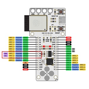
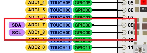
I2C bus consists of two signals (apart from VCC and GND): SCL and SDA. SCL is the clock signal, and SDA is the data signal. In class we connected 2 Barduinos (ESP32-S3) with wires. To make the 2 boards communicate I needed to find out the SDA and SCL pin to create wired communication between them. After checking the pinout we used pin 8 and pin 9 and GND. See pinout:
Then we decided for 1 Barduino to be “parent/master” and the other to be “child/slave”. We created the code together in class, installed the necessary library: “wire.h”and where then able to upload code that made it possible to do a Blink test and commuicate back and forth between the 2 boards
(See the modyfied code for parent and child below)
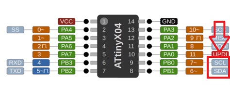
After succeding with this exercise I tried to make a connection between a board that I had made earlier and a Barduino. The board I had made has a Attiny1614 on it. See pinout here:
I used the same workflow as we did in class. But at first nothing happened. I noticed that the soldering on my board was poor and with help from my instructor I located where the problems were and resoldered. I uploaded the code again where the Attiny1614 was “parent” and the Barduino was “child”. Now the blink code worked.
Here are the files with the code for "Parent" and "Child"